Abstract
This tutorial is an example of how you can build a synthesizer with Native Instruments Reaktor.Table of Contents
To get the sounds you want you have to know how to build and create them. An easy and fast synthesizer to use is the Clavia Nord Lead. It's available with a keyboard or in rack version. The sound is excellent and it has many features, but of course not as many as you want. Only one thing to mention, mine has a limit of 4 voices, wich if you're playing chords with a long release time, you're stuck with a huge polyphony limit.
Let's simulate a Nord Rack in Native Instruments Reaktor.
Rebuilding an existing synthesizer probably won't give you a sound that wasn't created before because that's what the original does, but maybe it's a good way to get a better understanding of Reaktor.
First we have to know the specifications of the Nord Rack, so we have a basic thought of modules we'll have to use.
It has 2 oscillators.
- OSC 1
- waveforms: triangle, saw, pulse
- FM Amount
- OSC 2
- waveforms: triangle, saw, pulse, noise
- Keyboard Tracking on/off
- Semitones setting from -60 till 60
- Fine tune in cents
- Other oscillator features
- There is also knob for Pulse width modulation for OSC 1
- Mix knob for the OSC 1 and OSC 2 levels
- Sync button OSC 1 -> OSC 2
Knowing this, we can try to implement these features, step by step. Let's look further to get a global overview.
- Amplifier
- ADSR for the Volume Envelope
- Gain knob to control overal output levels
- LFO 1
- Rate and Amount
- Destinations: OSC1+2, OSC2, Filter, Pulse Width
- Waveforms: Triangle, Saw, Random
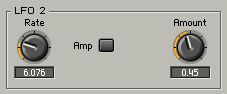
- LFO 2
- Rate and Amount
- Destinations: OSC1+2, Amplitude, Arpeggiator, Echo
- note: Because Arpeggiators are a topic on their own, I'm not going to implement this feature. On the real Nord Lead I don't use it either anyway. The same goes for echo, rather built a dedicated Delay effect or use a plugin.
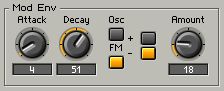
- Modulation Envelope
- Attack and Decay
- Destinations: OSC 2, FM Amount
- note: Instead of using a control which goes from negative to positive. I'm gonna use a positive control only in combination with a +/- switch.
- Filter
- ADSR to control the Filter Envelope
- Envelope Amount
- Filter Cutoff
- Resonance
- Keyboard Tracking On/Off
- Filter Types: HP 24dB, BP, Notch, LP 24dB, LP 12dB
This seems to be a long list but at the end there are not so many knobs to control, as you would expect of today's software synthesizers. The main reaon why I've chosen to rebuild a Nord Lead is because it's very fast and easy to use. And, because it is capable to generate a huge range of different sounds. From strings to some UFO effect or even a bassdrum, when the Nord Rack is finished you can create those sounds within minutes.
I hear you wondering, will it sound as the original instrument? No, because our synth uses Reaktor's Oscillators, not those from Clavia. However, don't let this disappoint you, it sounds good enough. Remember that this simulation will be different from the original.. as said before, I'll skip the Arpeggiator part. Some other things too, ie. the Octave shift switches for the pitch. A poly/mono/legato switch too. Actually these are essential, but you can't get it all at once. Adding these later remains an option.
While learning Reaktor, there were situations that I got stuck. I had to go back several times and change things. This can be frustrating because most of the time there are a lot of wires. Disconnecting them, removing, changing and adding modules,... this can be an unpleasant task. Especially when you mess things up, even badder then it already was before, and forgot how it was connected in the first place. To avoid messing around, it won't hurt to think before you act. On the other hand, without trying things you will never know if it will work. What I'm trying to say is that you get in trouble anyway. Only saving your work regurarly helps you out. Of course you already knew this from other programs in general.. . Time to start building.
Disclaimer: Be careful when using Reaktor and try to keep the volume in your audio setup at a reasonable level, unless you are very sure that your sound won't do things you don't expect to happen. You can destroy your speakers or crash your computer, even both. Everything you do with this tutorial is at your own responsability. Also, this isn't the best or optimized way to built the synthesizer and I even can't guarantee it will work for you. This document actually isn't a tutorial and I recommend learning Reaktor from other sources. It mostly describes the path I went trough to eventually get the Nord Rack.
Fire up Reaktor and Open a New Ensemble.
Delete the existing Instrument from the [Ensemble - Structure] because we want to start from scratch. (Insert Instrument > _New - Empty)
Give it Nord Rack as a name or anything else that you like. Double click on the Nord Rack to get in the [Nord Rack - Structure] , wich is empty, at least for now.
The Nord Rack receives MIDI thus let's add a NotePitch (Insert Module > MIDI In > Note Pitch) and a Gate (Insert Module > MIDI In > Gate).
It needs an Out Port (Insert Module > Terminal > Out Port) to connect to the Audio Out in the "Ensemble - Structure".
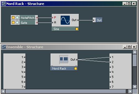
It doesn't really matter in what order you insert these modules in the structure, as long as you connect them correctly. But we were building the OSC 1 so let's do a test with a Sine Oscillator (Insert Module > Oscillator > Sine) and insert him.
Connect the:
- NotePitch to the P input of the Sine.
- Gate to the A input of the Sine.
- Out of the Sine to te Out Terminal.
- And yes, also the Out of the "Nord Rack" Instrument in the Ensemble - Structure to the 1 and 2 output ports of the Audio Out.
You should have something like this.
Now you can play notes with your computer keyboard. On an Azerty keyboard the DO note (pitch 60) is the "w" key (Qwerty, DO = "z")
Of course a Sine isn't enough what we want. We need a switchable triangle, saw, pulse. It would be nice if we'd have a seperate Macro for this.
Open a New Macro (Insert Macro > _New - Emtpy) and give it the name OSC 1.
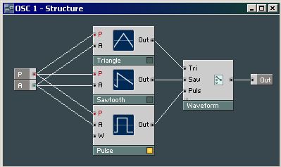
Add the Oscillators, 2 Input Port Terminals (one for P(itch) and on for A(mplitude)), name them A and P. And add 1 Out Port Terminal.
Don't forget a switch (Insert Module > Panel > Switch). Change the Switch Properties "Min Num Port Groups" from 1 to 3 because you have to connect the 3 Oscillators to it. Give the Switch the label "Waveform" and name its inputs.
Connect the P and A terminal to the P and A inputs of the Oscillators. You should now have something like this for the OSC 1 Macro Structure:
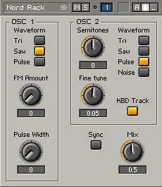
Replace the Sine.. with the new OSC 1 Macro. Now go the [Ensemble - Panel] and there you have your basic OSC 1.
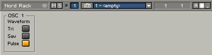
Note: if you don't see the buttons show up in the Panel, go to the OSC 1 Marco properties to make sure that "Visible" is enabled (and optionally Line Frame).
Tip: you can do it now or later.. Add a Pulse Width Modulation knob. Do this by right clicking on the "W" of the Pulse oscillator and select "Create Control".
Oscillator 2 of the Nord Lead is almost the same as OSC 1, but it has noise as a 4th waveform, semitones control, fine tuning, and keyboard tracking on/off features.
Duplicate OSC 1, name it OSC 2, and go into the Macro. Add a Noise Oscillator (Insert Module > Oscillator > Noise) and add a Noise input on the Switch. Connect the wires. That's it for the waveform generators.
But now, how to handle the pitch? It is controlled by the user playing a note, a semitone setting, and the fine tune. This can be done by using the "Add" module from the Math sect1. Go ahead and (Insert Module > Math > Add). Add an extra input to that module like you did with the Switch for selecting the waveforms (properties, Min num port groups).
Connect the P to the first input of the Add module, and create 2 controls for the other inputs. This will be the semitones an pitch, so give them some name you and a synthesizer would like. Now... beware, the range of those controls must be changed: the Semitones is a range from -60 till 60 (in 120 steps), and the fine tune goes from -1 till 1 (in 100 steps). Fix this.
Now that we are in this part, why not implement the keyboard tracking: put a switch between the P terminal and the input on the Adder. But something odd jumps in again. We want to have a static pitch when the KBD Track button is disabled, but the pitch jumps some octaves down. We need a range from 0 - 127 at the pitch input for the actual Oscillator, but we have value 60 from the note input and a 60 from the Semitones parameter. This gives 120, way to high. This can be solved by substracting 60 from the NotePitch value before the Switch. Or what are the keyboard values actually in NotePitch.. is the z on a Qwerty value 48? Just experiment with it and you will see. The original Nord Lead doesn't have a range from 0 - 127 but from -60 till 60 (or even 72 but this will do), so for the Semitones parameter we must add the value wich we substracted first.
I've chosen these settings
Semitones: min -64, max 64, default 0, 128 steps
Fine Tune: min -1, max 1, default 0, 200 steps
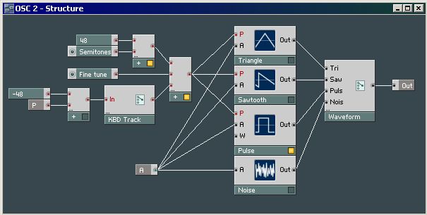
Just make sure the Pitch for OSC 2 is in balance when you dis- or enable KBD Track.
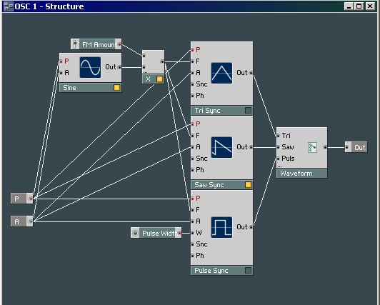
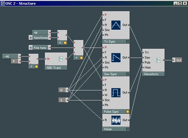
A neat feature of the Nord Lead is that it is capable of applying Frequency Modulation to Oscillator 1. In Reaktor, oscillators can be frequency modulated by the "F" input on the oscillator modules. But when looking at those in the OSC 1 Macro, there aren't any. That's right, they're wrong. To be able to implement FM, you should use the FM Oscillators. If you'd read the features carefully, you should have already known that this was needed and you might have chosen them in the part of OSC 1 already. If not, now it's the time to replace them. By the way, how about the Sync we're going to need? Correct, don't choose the FM's but the Sync's, unless you want to replace them again. The Sync oscillator's have -both- FM and Sync features so this is the best choice. Knowing this...
Replace the existing oscillators in the OSC 1 Macro with a Saw Sync, Tri Sync and Pulse Sync from (Insert Module > Oscillator).
Now the FM Amount part. In the real Nord Lead, OSC 2 acts as the modulator for OSC 1. This info is in the manual but I don't have more details, thus I'm afraid I have to use a Sine Wave and implement it as a modulator for the carrier, OSC 1.
What we need is an FM Amount knob to control that oscillator's A(mplitude) input. The output of this "Modulator" goes to the FM input of the "Carrier". Attention: If you go over the "F" input of an oscillator with your mouse, you read in the popup that this needs a typical range from. 0 - 5000. The output of an oscillator is between 0 and 1 (if ie. the A input was a Gate), so you have to do some math to correct this... use a multiplier. Insert these components. (Module > Oscillator > Sine) and (Insert Module > Math > Multiply)
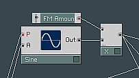
The X goes to the F(requency) inputs and the P and A get their P and A terminal connected. And there you have the FM Amount controller.
When a note is triggered, OSC 1 and OSC 2 start playing. But their waveforms loop differently in time. By Syncing OSC 2 as a slave to OSC 1, OSC2's waveform will be synchronized to OSC1.
The oscillators are 2 different macro's, both with only one audio out terminal. Adding an extra "out terminal" in OSC 1 and an extra "input terminal" in OSC 2, we can get the sync connected. The problem is we don't have S inputs in the OSC 2 Macro. Fix this by replacing the standard oscillators by the Syncs in (Module > Oscillators). Fun, isn't it? Right.. because in *the analog world* you would have a bunch of wires in your hand without knowing you're destroying one that got under your chair.
We will also need a switch to enable or disable the Sync (Module > Panel > Switch). Give it the name Sync.
Now just connect the "Out" of OSC1 to the Sync(switch) "in", and the Sync's output to the "S" input of OSC2. Done.
We have 2 oscillators, OSC1 and OSC2. So it would be cool if we can mix the volumes of their sounds. Maybe we can use some "mixer" module for this, but I'm going to use the "Crossfade" module. (Insert Module > Signal Path > Crossfade). Stick it somewhere behind the OSC1 and OSC2 Macro's in the Nord Rack's Structure and the Out terminal. Create a Control at the X iput of the Crossfade and call it "Mix".
We have a working Nord Rack, and if everything went well you have a decent basic sound.
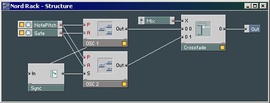
An OSC 1 Macro, with Frequency Modulation, Pulse Width Modulation for a Pulse and 2 other oscillators, with a switchable Waveform.
OSC 2, with an extra Noise oscillator, Semitones and Fine tune control and a Keyboard Track switch.
To eventually, get this little thing.
Is everything OK now? Yes and No. Later we have to implement the LFO's and you can't get around coming back into these Macro's. Some less and more important changes will have to be made.
The Nord Rack has 5 filter types.
- Low Pass 12dB
- Low Pass 24dB
- High Pass 24dB
- Notch Filter
- Band Pass
The filters have an extra setting, just as for pitch, Keyboard tracking
We're going to need a bunch of filters, let's put them in a New Macro and call it Filter. Note that the Notch Filter on the Nord Lead is a combination of a Notch and a Low Pass 12dB Filter. They say this sounds better than only a Notch Filter. Because this combination was the filtermode on that synthesizer I used most of the time, I think it's a nice challenge to remake this and see what result it gives.
This Filter Macro will need at least one In Port (Insert Module > Terminal > In Port) for the audio signal... And yes also an Out Port (Insert Module > Terminal > Out Port).
Of course add the filters! I've taken some from the Modules and saw wich one seemed useful. Get them from (Modules > Filters)Maybe these will answer the requirements:
- Multi/LP 4-Pole
- Multi/LP 2-Pole
- Multi/Notch 2-Pole
Between these ports come the Filters and the Switch (Insert Module > Panel > Switch), name that Filter type. Also add a Switch for the KBD Track.
The connecting shouldn't be difficult if you understood previous parts. "Create Control"'s for the P and the Res(onance). For the special Notch Filter, I think a mix from 2 filters can be used, done with the (Module > Math > Add)
Note: Again, also the Filters need LFO input, but it isn't here (yet). If you think you will need the FM filters instead, you are right. Well I needed them in the end, I don't know if you do. Really, there are and must be several ways to make it sound the way you want.. As for now I don't know what's the best. There are also Envelopes in the Modules list, waiting to be used or abused.. Just keep it sounding and you won't lose the motivation to expand your synthesizer. After all that's what Reaktor is, an expandable synthesizer.
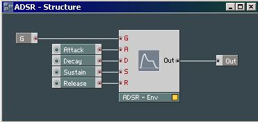
As found on almost every synthesizer, also our Nord Rack will need A(ttack), D(ecay), S(ustain) and R(elease) control. The Volume will also need an ADSR, so let's make a Macro for it so we can reuse it.
Create a New Empty Macro and call it ADSR. Give it an "In Port" terminal and name it G (from Gate) and an "Out Port". Add a ADSR module (Insert Module > LFO, Envelope > ADSR) and "Create Control" its inputs so it has an Attack, Decay, Sustain and Release control knob on the panel.
But, because the Filters will be FM modulated, we actually going to need the types wich support FM. Change the existing filters with their respective FM types. Their F input will be used for the FM, their P input for the Keyboard Tracking. Probably there are more ways to connect these components for the desired effect. Note that the F needs another range than the P inputs, so we have to use some math again with a Multiply and Add Module (Insert Module > Math > Multiply).
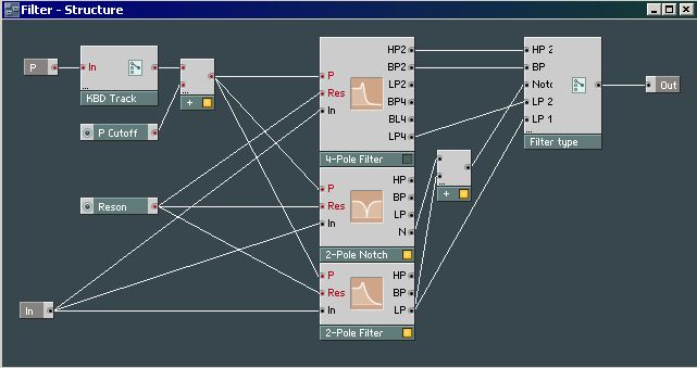
To make some faster progress in this tutorial and don't waste too much time, Here's how I did it.. The final Filter Structure.
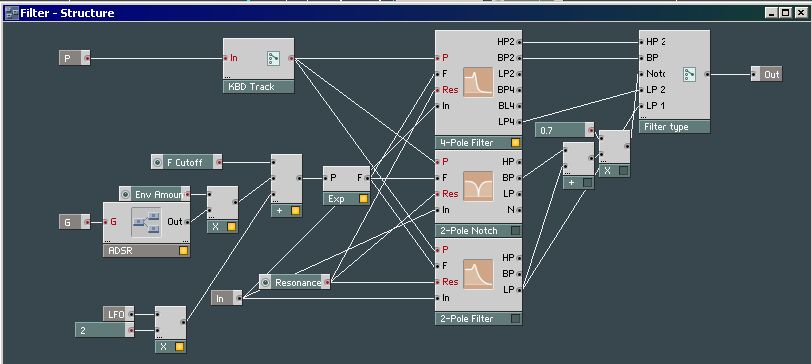
What you see here are
- the In Ports P(itch), G(ate), LFO, In (for the audio stream).
- The Gate goes through an ADSR Macro and that level is multiplied by the Envelope Amount.
- These levels are Added with the Filter Cutoff Frequency, and go through a (Modules > Math > Expon F.), this will convert the Pitch level (range 0 - 127) to a Frequency in Hertz.. which is used at the F input level of the Filters
- The P In Port goes to the KDB Track Switch, this will simply make the Pitch of a played note influence the P level of the filters by its value, or not when it's turned off.
- Resonance speaks for itself
- The Filter Type Switch too, but watch out for the volume level of the BP and LP outputs (that create the Nord Lead Notch), they are too loud together, 70% of that sounds good to me.
- The LFO is multiplied with 2, to get higher and lower peaks.
And now it's getting interesting in the panel..
This one is easy, just copy the ADSR Macro from the "Filter - Structure" to the Nord Rack - Structure and put it after the Gate. Connect the Out of the ADSR to the A inputs of OSC 1 and OSC 2. At least for now that is.
The Nord Lead has 2 LFO's and guess what, we're gonna start with building LFO 1. It has 3 waveforms. A Triangle, Saw, and Random. Further it has an Amount knob and a Destination knob. On my Nord Lead the destinations can be OSC 1 + 2, OSC 2 alone, Filter, or Pulse Width.
To keep a clear overview in the Reaktor Structures.. it's a good habit to group as many components as you can in the Macro they belong too. The drawback is that you have to go deep inside structures to get where you want to be, but it helps to understand the overall sound travelling trough the synthesizer components. In practice this means, that maybe it's better to put a Switch *inside* the LFO Macro than outside it (thus in the main structure).
There are existing LFO Macro's.. But we're building our own synth. The "problems" I see with the existing ones is that they don't have the corresponding waveforms. Also 4 outputs might be useful.
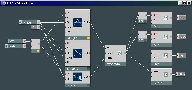
- The Pitch/Rate of the LFO's (Tri, Saw, Random) will be controlled by a Rate Knob added with -72. This will generate a good speed.
- An Amount knob is assigned to the A inputs to control the level of the LFO effect.
- Only one input port needed, the Snc (Sync) makes the LFO's start their cycle when a note is triggered.
- A Switch named Weveform is placed between the Oscillators and the Output Ports Terminals
- These outputs can be turned of with Switches for every channel. Hah, the real Nord Lead can only assign the LFO to *one* destination... This example can assign it to *all* the Outputs. An Audio to Event Controller must be added to for the OSC 1 and 2 Terminals.. This depends on what inputs those terminals are connected too. That's why the Filter and P.Width don't need it.

The second LFO of the Nord Lead has the 2 casual controllers Rate and Amount. It can also be used as an Arpeggiator. The assignments are OSC1+2, Amp, Arp UP, or Arp down. Further there's an Echo effect and a Random Arp. I'm not going into the Arpeggiator analysis because this is a sequencer and it should deserve a separate tutorial or document. Building an Amplifier LFO in Reaktor will do it for now.
You're maybe thinking that just connecting the output of an LFO to the amplitude of an Oscillator will do what you want. Well, maybe it does. But this isn't how the real Nord Lead sounds. For pitch this approach could be ok: Let's say you play a note with Pitch 60, the LFO starts working.. The result will be (and mostly this is what you want) that when your LFO Amount is 4, the pitch will travel between 58 and 62. For Volume this is a bad idea, the signal shouldn't get louder than it is without the LFO.
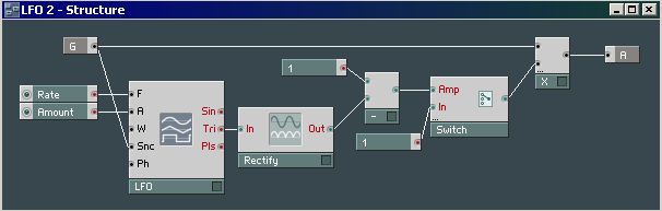
- An Amount (0 - 1), Rate (0.1 - 25) that control the LFO Module
- I took the Triangle as waveform output
- The problem as explained above, LFO's generate a signal from negative to positive.. better don't do this for the volume. By using a Rectify module (Modules > Math > Rectify), the range goes from 0 - n. The square root of 25 = 5, and the square of -25 = 5 too. Excellent, now the LFO does what we want.
- But, the sound must go from loud to silent when fading in the Amplitude Modulation effect. That's why I substract 1 with the output of the square root previous.
- This goes to the Amp input of a Switch, when this is turned off, 1 is used as a constant.
- Multiply this with the signal at the input (G), and you will have a smooth volume modulation between 0 and 100% of that sound, and a range from 0.1 and 25Hz.
Have to admit, much work for these three controls, but it's worth it for the audible result!
Three controllers/knobs, Attack, Decay and Amount (both negative as positive). The possible destinations are a switchable OSC 2 or FM Amount.
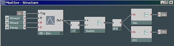
Finally...
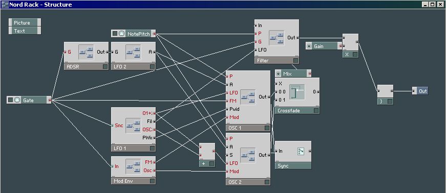
- The Gate goes to an ADSR, Sync LFO 1, Mod Env, the Filter, and the FM Oscillator in OSC 1
- ADSR goes to LFO 2. This will make the LFO 2 a Sync slave from the ADSR and the audio signal is mixed
- LFO 2 goes to the A(mplitude) inputs of OSC 1 and 2.
- The 4 outputs of LFO 1 go to the corresponding inputs of the Oscillators.. and the Filter. The Add module that goes to the LFO input of OSC 2 simply sits there because you can't connect 2 wires to it.
- Mod Env has the destinations FM and OSC, and routes to the Mod(ulation Envelope) inputs of OSC 2 and OSC 1. In OSC 2 it will modulate the FM Amount.
- The NotePitch module drives the P(itch) inputs of OSC 1 and 2, and also the Filter (used for Keyboard Tracking).
- The Out of OSC 1 goes to the In of the Sync (switch), and the output of the Sync goes to the S input of OSC 2.
- The Crossfade's inputs come from OSC 1 and 2, and the output of a Mix Control knob.
- The Crossfade's output goes to the In of the Filter.
- This signal gets multiplied with a Gain (range 0 - 1.1), enters the voice combiner and there's your sound coming Out of your Audio Card.
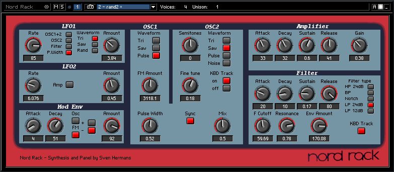
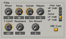
Some fun with the Appearance of the knobs (labes yes/no), changing the colors of the buttons and loading a Picture gives this result,